Circuits and logic?
You might be confused — when I talk about logic circuits I’m not talking about circuit boards, I’m talking about pictoral representations of logical expressions. On WYSE tests, they may give you a circuit and ask you what expression the circuit represents. Because each situation is different, I will show you what each object on a circuit represents and I’ll give an example of the thought process of reading a circuit.
The objects of a circuit
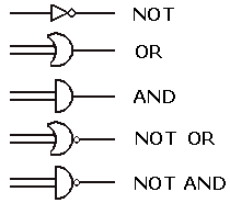
Remember: In a logic circuit, we’re still using AND, NOT, OR, XOR, etc. except we’re doing it through a picture. Below shows you how to represent the logical keywords in pictoral form.

The difficulty in circuits is not from figuring out what each object does, but in what order to read the circuit.
Reading a circuit
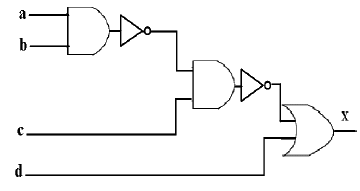
Below is a circuit diagram from the Computer Science WYSE 2003 Sectional. This was taken from their Academic Challenge webpage.

Sometimes there will be a solid black dot, which designates where you should begin; however, in this case we can just start going and it’ll all work out. At the top left we start with A AND B, but there’s a NOT lurking right after that, so we actually have NOT(A AND B). The result is AND’ed with a C (just follow the lines), but there’s a NOT after this AND too, so our result is NOT(NOT(A AND B) AND C). Finally, we take that result and OR it with D, and the value of X (which is the final result of the circuit) is NOT(A AND B) AND C) OR D
Conclusion
Circuits get a lot crazier, so just be patient with them. If you want to get better with circuits I’d recommend looking at other examples on WYSE tests and figuring out all the patterns. On a most basic level you just follow the lines, but sometimes they have a tendency to run into eachother and just make a mess.
Previous: Prefix, Infix, Postfix
Next: Back to Table of Contents


